
PicoSource AS108 Overview

Professional and portable performance at low cost
The PicoSource™ AS108 Agile Synthesizer generates signals to meet the needs of both benchtop and integrated module applications. Its broad 300 kHz to 8 GHz frequency range, fast settling and programmable phase, frequency and amplitude match it to a wide range of applications, with the added advantages of low cost, small footprint and 12 to 15 V power requirement.
The AS108 has professional-grade performance that is effective in both static and parameter-agile applications, making it a bench or field instrument for developers, scientists, educators, students, and service and installation technicians. Its speed, external clock referencing, trigger capabilities and user-programmable power-up mode all suited to system integrations such as automated test, unmanned installations and multi-signal stimulus.
The AS108 is a full-function USB-controlled vector (IQ) modulating signal synthesizer. It is supplied with a clean, easy and efficient user interface for controlling its amplitude, frequency and phase agility; including modulations, sweeps, hopping and list modes from Microsoft Windows. Multiple synthesizers can be controlled from multiple instances of the software running on a single controlling PC or device. Remote control is also possible using the API included.
PicoSource AS108 Features

Specification highlights
- 300 kHz to 8 GHz operation
- –15 dBm to +15 dBm dynamic range
- Fast 55 μs frequency settling time to 10 ppm
- Fast amplitude settling: < 25 μs to 1 dB and < 200 μs to 0.1 dB
- Sweep, hop and list of frequency and level or list phase and level
- −100 dBc/Hz phase noise typical at 1 GHz and 10 kHz offset
Powerful and capable
- FM, ØM and AM modulation, internal sine or external input
- External reference clock I/O and trigger I/O
- Use sweep lists to emulate schemes such as QPSK, QAM, ASK, FSK
- Adjustable dwell and trigger sweep or trigger next point modes
- Work in and convert units of measure to suit application
- Programming examples for LabVIEW, C, C#, Python, MATLAB
- Suited to bench, field and system integration applications
- USB-controlled from Windows PC and display or tablet
- Touch, mouse, keyboard or remote interface software (API included)
- Multi-unit operation with synchronized modulation, sweeps, hops and lists
- Configurable stand-alone operation mode
Remote control operation
The PicoSource AS108 is supplied with a DLL that allows you to control the device from C and C-compatible languages and applications such as C++, C#, Python, Keysight VEE, National Instruments LabVIEW and MathWorks MATLAB.
Download the SDK (go to PicoSource > PicoSource AS108 > Software > PicoSynth 2)
Multiple device operation
You can control multiple AS108 signal synthesizers from a single PC by running multiple instances of the PicoSynth 2 software. Each time you start a new instance of PicoSynth 2, it will list all compatible connected devices that are not yet being controlled. You can then select any device in the list for connection.

Demonstration mode
The “User Interface Demo” device is always available in this list and allows PicoSynth 2 to run for demonstration purposes without a connected device. You can use this mode to try out the software before buying a device.
PicoSource AS108 Software

PicoSynth 2 software
The PicoSynth 2 software presents a clean, efficient, touchscreen-compatible user interface for direct and convenient access to synthesis parameters. These can be typed, scrolled or stepped by a configurable increment value, in a selectable unit of measure such as dBm, mW, V RMS, V pk-pk or degrees and radians. Its flexibility matches or exceeds that of the traditional control panel of a benchtop synthesizer.
The controls are presented in three independent parameter tabs, each of which holds separate settings for convenient mode switching:
- Carrier wave and basic modulations
- Sweep or hopping of parameters
- Arbitrary list of parameters
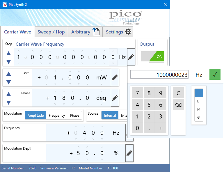
Carrier wave and basic modulations
Set carrier wave frequency, level and phase using typed values or scrolled digits, or by stepping by an increment of your choice, and then enable the output. When required add frequency (FM), phase (ØM or PM) or amplitude (AM) modulation using internal sine modulation synthesis or an external DC-coupled source connected to the front-panel BNC interface. Modulations are derived from digital IQ modulation and the external trigger output (rear-panel BNC) is synchronous with the internal modulation source.

Sweep or hop parameters
Set up sweeps and hops between two parameter values: start of sweep and end of sweep (stop). Either can be the higher value. Set the number of points in a sweep (between 2 and 10 001 points). The dwell time then defines a duration for which each point in the sweep will be output. PicoSynth calculates and displays the duration of the whole sweep and the linear step size between each point. A bidirectional sweep will sweep from the start to stop and back to start in completing a single sweep of the parameter. A hop is a limited case of sweep in which there are only two parameter values that are alternately output.
The AS108 can sweep or hop the frequency, level or phase parameter. It can also sweep or hop two parameters at the same time: frequency and level, or phase and level. This allows, for instance, a simple linear flatness or loss-compensating profile to be applied to a sweep or hop, perhaps increasing output level as frequency increases. The example shown applies a 5 dBm increase in level as the frequency sweeps from 1 GHz to 2 GHz. Sweeps and hops can be synchronized to external events and instruments using the external trigger input and output (rear panel BNCs) or software trigger. Trigger occurs at, or initiates, a sweep start or next point in sweep. This synchronization flexibility can be of particular value to high-speed system sequencing in, for example, high-speed test.

Arbitrary parameter list
Import a parameter list file to generate an arbitrary sequence of frequency/level or phase/level points. The file is in a straightforward comma-separated values (CSV) format that you can create using any text editor or export from a spreadsheet program.
PicoSynth 2 shows a summary of the file contents to help you verify that you have selected the correct file. You can program the dwell time (time between points) and trigger mode.

Save, recall and other settings
Parameter step increment values and the saving and recall of user settings are found under the Settings tab.
You can also save to the device a modified or custom power-up setting, allowing the signal source to power up in a known state without further connection or control over USB.
Data Sheets:
User’s Guides:
Programmer’s Guides:
Quick Start Guides:
PicoSource AS108 Specifications
| General | ||
|---|---|---|
| Standard conditions are ambient temperature between 15°C and 30°C, 20 minutes after power-up. |
| Carrier wave | ||||||||||||||
|---|---|---|---|---|---|---|---|---|---|---|---|---|---|---|
| Parameter | Applicable range and values | Condition | ||||||||||||
| Frequency range | 300 kHz to 8.192 GHz | |||||||||||||
| Frequency resolution |
| |||||||||||||
| Frequency settling time |
| to ±10 ppm | ||||||||||||
| Frequency accuracy (internal reference) | ±5 ppm | |||||||||||||
| Output power range | −15 dBm to +15 dBm | |||||||||||||
| Output power resolution | 0.1 dBm | |||||||||||||
| Output power setting accuracy | ±1.5 dB | |||||||||||||
| Output match (VSWR) |
| |||||||||||||
| Output amplitude settling time |
| |||||||||||||
| Output protection | 25 V DC pk and 20 dBm | |||||||||||||
| Phase noise at 10 kHz offset |
| |||||||||||||
 | Measured phase noise at 1 GHz | |||||||||||||
| Harmonics |
| Output power set to +10 dBm | ||||||||||||
| Sub-harmonics |
| Output power set to +10 dBm | ||||||||||||
| Spurious |
| Output power set to +10 dBm | ||||||||||||
| Sweep, hop and list modes | ||
|---|---|---|
| Parameter | Applicable range and values | Condition |
| Sweep, hop or list parameters | Frequency; level; phase; frequency and level; phase and level | |
| Discrete sweep or list points | 2 to 10 001 (or 2 to 1750 points when saving power-up settings to device) | Hop is a special case of sweep with only two points. |
| Frequency stepping dwell time | 27 to 65 500 µs (or 27 µs to 1750 µs when saving power-up settings to device) | Excepting any step exceeding ±2.2 GHz to or from the frequency band 7.0 GHz to 8.0 GHz, minimum dwell 100 µs. |
| Modulation | ||||||||
|---|---|---|---|---|---|---|---|---|
| Parameter | Applicable range and values | Condition | ||||||
| Frequency range internal sine source | 10 Hz to 5 kHz | |||||||
| Internal modulation sample rate | 37 kS/s | Sampled sideband spurs are generated at 37 kHz offset. At 1 kHz modulation typically < -30 dB relative to sidebands. | ||||||
| Frequency resolution and accuracy | 1 Hz resolution ± 0.1% accuracy | |||||||
| AM depth range |
| |||||||
| FM deviation | 2% carrier frequency or 200 kHz maximum | |||||||
| PM deviation | ±180° | |||||||
| External modulation input bandwidth | DC coupled to 10 kHz | |||||||
| External modulation input sampling | AM: 125 kS/s FM/PM: 89 kS/s at 12-bit resolution | Sampled sideband spurs are generated at 125 / 89 kHz offset. At 1 kHz modulation typically < -50 dB relative to sidebands. | ||||||
| External modulation input sensitivity |
| for selected depth or deviation | ||||||
| External modulation input protection | ±5 V DC + AC pk | |||||||
| Synchronization I/O | |||||||
|---|---|---|---|---|---|---|---|
| Internal 10 MHz reference output |
| Into 50 Ω | |||||
| External reference input |
| ||||||
| External reference lock range |
| ||||||
| Trigger input threshold voltage |
| ||||||
| Trigger output logic levels |
| Into 1 kΩ Into 50 Ω | |||||
| Trigger output rise and fall times |
| Into 50 Ω | |||||
| Trigger in to trigger out delay |
| Gives a lead of 17.5 µs to frequency / phase step, 37.5 µs to a level step. | |||||
| Trigger out to triggered event delay | 17.5 µs typical | Frequency or phase step | |||||
| 37.5 µs typical | Level step | ||||||
| Dwell period holds off (prevents receipt of) a further trigger. | |||||||
| Trigger input protection | ±10 V DC + AC peak | ||||||
| Trigger output protection | ±4 V DC + AC peak | ||||||
| Reference I/O protection | 4 V AC p-p ±15 V DC | ||||||
| Miscellaneous and environmental specifications | ||
|---|---|---|
| Power requirements | +12 V to +15 V DC, 12 W, 2.1 mm jack, centre pin positive | |
| Control interface | USB 2.0 | |
| Dimensions | W 173 mm x L 232 mm x H 56 mm | Excluding connectors |
| Weight | 1.78 kg | |
| Operating environment | +5°C to +40°C, 80% RH non-condensing, Pollution Degree 2 | |
| Storage environment | −20°C to +50°C, 80% RH non-condensing, Pollution Degree 2 | |
| Vibration tolerance | 0.5 g | 5 Hz to 300 Hz |
| Safety | Declared conforming to: EN61010-1:2010 and EN61010-2-030:2010 Safety requirements for electrical equipment for measurement, control and laboratory use, general requirements and for testing and measuring circuits. | |
| EMC | Declared conforming to: EN61326-1:2013 Electrical equipment for measurement, control and laboratory use – EMC requirements. Group 1, Class B. (Emissions) EN61326-1:2013 Electrical equipment for measurement, control and laboratory use – EMC requirements. Basic Environment. (Immunity) EN61326-2-1:2013 Part 2-1: Test configurations, operational conditions and performance criteria for sensitive test and measurement equipment for unprotected applications. CFR 47 Code of Federal Regulations FCC: part 15 Subpart B – Frequency devices – unintentional radiators. Radiated emissions standard. Class A. | |
| Warranty | 3 years | |
| ECCN coding | EAR99 | |